CIRS 062MQA CBCT电子密度和图像质量模体
类别:CIRS模体
品牌:CIRS
销售热线:010-53326395,82067780
美国CIRS 062MQA CBCT电子密度和图像质量模体,CIRS 062MQA模体简介
The design intent of 062MQA is to provide a tool that can be used for both electron density calibration and image quality assessment of Cone Beam CT systems integrated in radiation therapy devices. The electron calibration function of the phantom enhances the outcome of the adaptive radiation therapy while the image quality features address the fine balance between optimizing image quality while minimizing radiation dose.
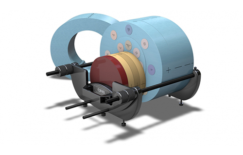
The 062MQA CBCT Electron Density & Image Quality Phantom consists of several sections: a 100mm thick body slab, a 100 mm thick CBCT Image Quality phantom, a 50mm thick Electron Density Phantom, and a Bolus consisting of a 37.5mm thick uniform slab, a 12.5mm thick uniform slab and a 50mm thick uniform slab.
The 100 mm thick body section has a central hole that receives the CBCT Image Quality Phantom. Each Bolus slab is drilled to accommodate an ion chamber insert and allow for ion chamber measurements regardless of the position of the Image Quality Insert. The thicknesses of the sections were selected to allow for positioning of any of the layers containing the Image Quality features in the central axis of the beam. Also sections of different thickness decrease the increment with which the electron density section can be offset from the central axis.
The phantom support along with laser alignment marks allow for easy and quick positioning of the phantom on the accelerator couch. The phantom is placed on the support rails with the help of machined grooves. Buffer plates are provided to decrease the artifacts from the support device and to allow the user to access the handles on the support plates. The leveling of the support and implicitly the phantom is done by adjusting leveling feet.


美国CIRS 062MQA特点:
-
Perform all CT Image QA tests for AAPM TG Report #1
-
Use ionization chambers for dose measurements
-
Perform dose measurements using Ion chamber
-
Calibrate Electron Density in multi-slice CT and Cone Beam CT
-
Perform central axis and off-set measurements
-
Position simulated tissue materials in CT & CBCT energy range at 17 different locations
-
Optimized for volumetric imaging
-
Quick positioning and customized loading configurations
The One Tool Solution for Electron Density Calibration & Image Quality Assessment
CBCT Image Quality Phantom
The Phantom is comprised of four layers: spatial resolution, CT number linearity/slice thickness, low contrast and uniformity. The positioning of the different layers of the CBCT Image Quality phantom at the central axis can be done with the phantom in the 100mm body section or with the phantom placed directly on the support device.

Spatial Resolution Layer
The Spatial Resolution Layer is designed to evaluate the spatial resolution of IGRT systems. Line pair patterns from 1 lp/cm to 16 lp/cm are embedded in the background. In order to minimize artifacts, each line pair pattern is made from a material with 350HU greater than the background attenuation. The line pair patterns are 3D patterns 12mm in height along the longitudinal axis of the CBCT Image Quality Phantom. The spatial resolution targets are arranged in a circular pattern.

CT Number Linearity and Slice Thickness Layer
The CT number Linearity and Slice Thickness Layer is designed to determine Contrast-to-noise Ratio, Hounsfield number accuracy and Slice Thickness Sensitivity. Six rods made of Air, Low Density Polyethylene (LDPE), Polystyrene, Acrylic, Delrin and Teflon are used to measure the CnR and Hounsfield number Accuracy. Three angled air channels arranged in an equilateral triangle can be used to assess Slice thickness sensitivity.
 Low Contrast Layer
The Low Contrast Layer is intended to assess the system's ability to detect small differences in contrast. It contains three sets of low contrast rods with linear attenuation differences of 0.5%, 1% and 2% relative to the background material. The diameters of the low contrast rods were chose to provide a 0.5 ratio between two adjacent rods by cross section and volume. Additional features are designed to evaluate the magnification on the orthogonal axes of the transversal image and as input for calculation of the Point Spread Function and subsequent calculation of Modulation Transfer Function.
 Uniformity Layer
The Uniformity Layer is designed to measure the system’s ability to produce uniform images across the field of view of an object with highly homogeneous physical properties in all directions.
Electron Density Phantom
The Phantom consists of nested disks made from Plastic Water?. The nested disks allow simulation of both head and abdomen phantom configurations. Eight different tissue equivalent inserts can be positioned at 17 different locations within the scan field. The geometry of the phantom also enables the user to take measurement offset from the central axis.
NOTE: This product or an optional accessory of this product requires a CIRS dosimetry cavity code before an order can be placed. Please refer to the Dosimetry Cavity Codes document to identify the CIRS code for the probe you intend to use with this product.